This semester, I wanted to take a step back from my previous focus on strictly machine learning related subjects and approach a set of topics which I had not yet had the opportunity to fully dive into. Those things being graphics programming and shaders, mechanism design and analysis (CAD), and physics. I like to approach each semester of my university education with a final project in mind from the outset, particularly one which represents a synthesis of the different topics that I am studying. Inspired by the Bullet physics engine, as well as this video, I set out to create a simple robotic simulator, and to designa and create a mechanism of my own alongside this software project. I did not initially set out to do all of the development in Rust, but after learning about the hardware abstraction layer built into the WGPU Library, It became an attractive choice for this.
3D Graphics in WGPU
The WGPU library uses the gfx-rs hardware abstraction layer to dispatch the rendering pipelines to the GPU, across all platforms. I developed the project between a Mac laptop and a desktop Linux computer, with NVidia graphics, and it worked splendidly to run both Metal and Vulkan, with no extra complications to the build system. Initial challenges I ran into using this library was the diffuculty of creating good abstractions, especially for uniform buffers, given the ownership patterns of different handles in the API. Learning this library alongside of OpenGL, the conceptual differences are mainly in the way that we must use a 'Device' object to interact with many of the API calls, as well as the 'Queue' and 'RenderPass' handles, which are used to send pipeline programs to the GPU. There was more setup involved than I anticipated. OpenGL's single-threaded nature allows for much more freedom in the how and when of dispatching various operations on GPU.
STL 3D Meshes in WGPU
For my purposes, the first order of business was parsing STL meshes, as this is the primary mesh format robotics and for CAD. This is a fairly straightforward process to parse the files, and then create the vertex and (optimized) index buffers for these. I then created the Transform type, consisting of a single 4x4 matrix to represent my homogeneous transforms. I utilized Rust's 'rayon' library in order to parellelize some of the operations necessary to manipulate the meshes. This is very useful, as a single threaded implementation will not utilize all CPU cores when running operations on each vertex.
Designing and Printing a Leg Mechanism in CAD
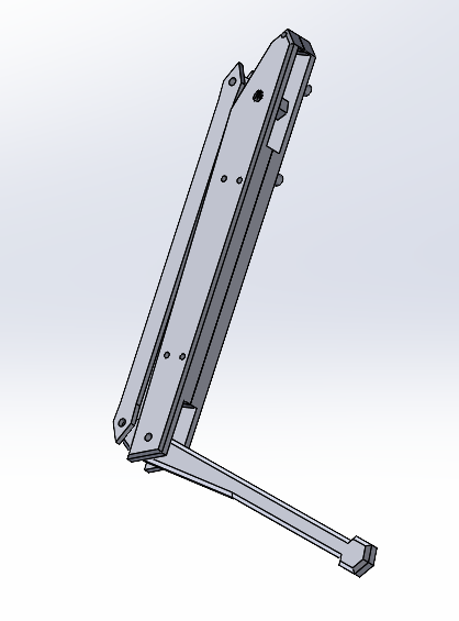
The quadreped leg mechanism that is used in robots such as the Spot or Cheetah designs, is a simple and elegant mechanism that uses a parallel mechanism to allow for two or three degrees of freedom of the leg to be controlled with motors in series. I modeled up a initial mechanism a few days after deciding on this project direction, with the main two proximal and distal links of the leg, two parallel links behind the proximal link, and a small connector set inside of a slot, controlling the parallel linkage. The main challenge in the design phase were making the main link fit all of the requirements that I needed in order to fit two servos. I began printing the designs just before Thanksgiving. I soon realized that there were some modifications that needed to be made in order to fit the servos on correctly, especially given the fact that I was just using a set of nuts and bolts, and not any more specific hardware. I had to split the main link (the "femur") into two parts in order to be able to assemble the thing correctly. I have to thank the university, and the people at the new makerspace in EXP for letting me print multiple iterations of my design. After some design modifications, I had a working leg mechanism assembled. I have some single-board computers already on hand, and the Beaglebone Blue was the perfect choice for this project. After purchasing the HiTec HS422 Servos, it was simple to setup and use the board's software to control the anolog servos directly from the board in linux, thanks to the Blue's Programmable Realtime Units (PRUs).

Reading URDF and Forward Kinematics
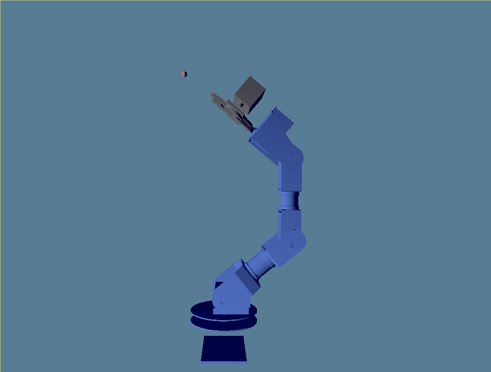
Armed with the xml-rs crate and the URDF specification, I began work on my parser. Rust's pattern match really shines here. With the XML Boilerplate taken care of, URDF translates fairly well to my data structures. Essentially, each link is a Mesh + Transform (visual and collision); each joint is a Transform. The next step is to walk the data structure, assuming it is a tree, and calculate the world-frame transforms for each link. Getting these scene graph transforms into the shader challenged my understanding of WGPU bind groups, but it turned out to be pretty simple. With this done, we are able to specify the "theta" for each joint, and articulate rendered mechanism in real-time!
In Progress & Future Directions
I had some trouble getting the leg design to export to URDF properly, due to the parallel mechanism, there doesn't seem to be an easy way to export it from solidworks using the existing tool. Given that my own code assumes the data of the robot is structured like a tree, I would have to make some non-trivial modifications before it would load correctly, and probably would also have to add a contraints solver if I want it to resolve forward kinematics. Next, I would like to work on more of the physics simulation aspects of this project, that are currently underdeveloped. I already have a good kinematics component; it should be pretty straightforward to build the dynamics and collisions. I am in the process of adding collisions so that should be in the next update probably. I am currently not using the inertial component of the links, so adding constraints on those would be a great thing to do as well. I will have to look into what can be done to get performance out of these things. I am interesting in using more compute shaders in my future projects